RS232 Communication Configuration
| Pin |
25-Pin Signal |
| 1 |
Chassis Ground (GND) |
| 2 |
Transmit Data (TD) |
| 3 |
Receive Data (RD) |
| 4 |
Request to Send (RTS) |
| 5 |
Clear to Send (CTS) |
| 6 |
Data Set Ready (DSR) |
| 7 |
Signal Ground (SG) |
| 8 |
Carrier Detect (CD) |
| 9-19 |
(not used) |
| 20 |
Data Terminal Ready (DTR) |
| 22 |
Ring Indicator (RI) |
| Pin |
9-Pin Signal |
| 1 |
Carrier Detect (CD) |
| 2 |
Receive Data (RD) |
| 3 |
Transmit Data (TD) |
| 4 |
Data Terminal Ready (DTR) |
| 5 |
Signal Ground (SG) |
| 6 |
Data Set Ready (DSR) |
| 7 |
Request to Send (RTS) |
| 8 |
Clear to Send (CTS) |
| 9 |
Ring Indicator (RI) |
       There are two general cable configurations used with the
       RS-232C Communications Standard:

       Data Terminal Equipment (DTE): printers, plotters, and
       pointing devices, generally communicate unidirectional.

       Data Communication Equipment (DCE): modems, communicate
       bi-directional, which is the reason for the reversal of
       Transmit Data (Pin 2) and Receive Data (Pin 3) for DCE.
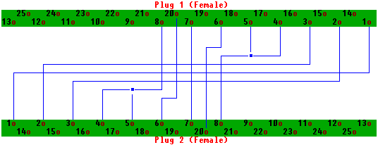
Computer to Computer Link (Laplink / Norton Commander)

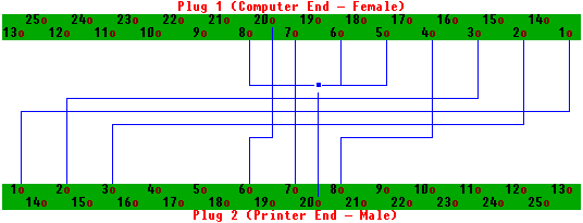
Computer to
Serial Printer

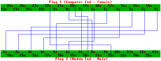
Computer to
Modem

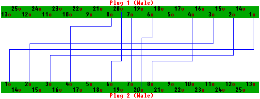
Modem to
Modem

|